
A Practical Guide to Selecting Geotechnical Data Acquisition Systems
Pierre Choquet, Dr.-Eng., P.Eng., Technical Advisor RST Instruments and Orica Digital Solutions, Maple Ridge, BC, Canada
Ali Siamaki, PhD, Principal Business Development Manager, Tony Gee and Partners, Toronto, ON, Canada
The geotechnical industry is undergoing a fundamental strategic shift, moving away from periodic, manual instrument readings, often called 'sneaker-net', toward real-time Automated Data Acquisition Systems (ADAS). This evolution has transformed our ability to manage risk by providing the continuous data streams necessary to detect critical trends before they escalate into failures. The purpose of this article is to equip engineers with a structured framework to confidently navigate the complex modern technology landscape and make informed, effective design choices for their projects.
However, the rapid proliferation of new connectivity options from LoRaWAN and Mesh networks to Low-Earth Orbit (LEO) satellites has created a paradox of choice, often leaving engineers uncertain about which system architecture best suits their project's unique constraints. The primary objective of modern instrumentation is not simply to collect data, but to ensure that data is delivered in a timely manner, enabling proactive risk management. To deconstruct this challenge, we will use a foundational architectural model that breaks any ADAS down into its core, universal components.
The Foundational Architecture of an ADAS
Before evaluating specific technologies, it is essential to understand the universal, multi-layered architecture that underpins any modern monitoring system. By breaking a system down into its core components, we can systematically address the design challenges at each layer. Every robust ADAS can be deconstructed into four fundamental layers or tiers, from the sensor in the ground to the server in the cloud.
The Sensor: This is the instrument in the ground that measures a physical parameter. Examples include piezometers, inclinometers, extensometers and strain gauges.
The Node (The Logger): This is the device that reads the sensor, digitizes its signal, and prepares the data for transmission. It can be wired directly to a gateway or act as a wireless endpoint.
The Gateway (The Aggregator): This component serves as the central hub, collecting and consolidating data from all the local nodes on site.
The Backhaul (The Pipeline): This is the internet connection that transmits the aggregated data from the Gateway to the cloud or a central server for storage, analysis, and visualization.
This architectural model provides a critical strategic insight: the complex problem of system selection can be simplified by breaking it into two distinct and manageable stages. The first is the "Last Mile" (the local network), and the second is the "Backhaul" (the global connection). We will begin by analyzing the technologies that comprise the "Last Mile."
Stage 1: Evaluating "Last Mile" Technologies (Sensor to Gateway)
The strategic importance of the "Last Mile" cannot be overstated. This stage of the architecture is concerned with reliably moving data from the sensor in the ground to a local collection point, the Gateway. The technology chosen for this task is primarily driven by the site's physical characteristics, such as topology and obstructions, as well as the project's specific data requirements, like measurement frequency and volume.
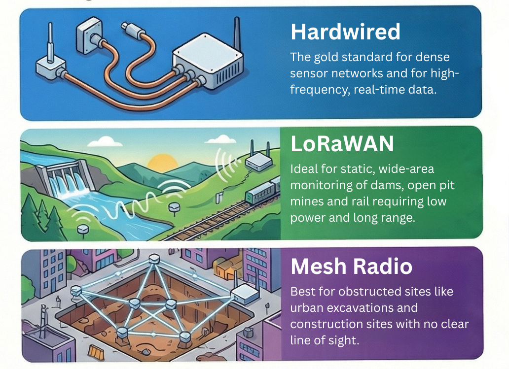
1. Hardwired (Cabled) Systems
Hardwired systems use physical copper cables to transmit signals, typically digital RS-485, analog 4-20mA or the frequency signal of vibrating wire transducers, to connect sensors directly to a central data logger. This method remains the gold standard for situations with high count of sensors in close proximity or for high-frequency applications like dynamic strain or pore pressure monitoring, vibration monitoring or for instruments like Automated Motorized Total Stations (AMTS) where the data bandwidth requirements exceed the capabilities of wireless technologies. Cabled systems using multi-channel dataloggers can in some cases be more economical when numerous sensors with relatively short signal cable lengths are connected to a single central data logger as compared to LoRaWan or Mesh nodes described below. Cabled systems are also often the only viable option in environments like tunnels with non-linear alignments where radio signals can only propagate over short distances, although the Mesh nodes described below can also be an option in that context as well. Cabled systems are also needed when reading sensors that require active power for heating or when complex onboard computations must be performed on site, for example to trigger additional readings or change the reading frequency, although similar capabilities can also exist in the LoRaWan or Mesh nodes as well.
The primary operational risk stems from this reliance on physical infrastructure; cables are highly vulnerable to damage from construction equipment, and installation costs can be prohibitive on large, sprawling sites. A second operational risk is the increased vulnerability of the network to lightning and high transient voltages. High voltages due to lightning strikes travel primarily at the ground surface radially from the point of impact. These high voltages along the path of horizontal instrument signal cables near or at the ground surface can generate currents in the range of several hundreds to thousands of amperes that travel instantaneously to the sensors at one end of the signal cable and to the central data logger at the other end, with the risk of damaging those components. Multi-stage transient and lightning protection external components often need to be added to cabled systems to properly protect them and to protect the instruments connected to them which can be expensive to replace if they are instruments embedded in the ground such as piezometers. An often overlooked aspect of these lightning protection networks is that they need to be properly grounded to be effective.
2. LoRaWAN (Long Range, Low Power)
LoRaWAN has become an industry standard for static, low-frequency monitoring applications. It employs a specialized radio modulation technique that enables data transmission over vast distances up to 15 kilometers with a clear line of sight while consuming very little power. This makes it the ideal solution for large-scale sites like water and tailings dams, large open pit mines or linear infrastructure projects such as pipelines and railways, where datalogger nodes must operate independently for five years or more on small internal batteries. LoRaWan benefits from its wide acceptance and popularity for several Internet of Things (IoT) applications so that prices have reduced considerably and allowed manufacturers to offer very low-cost datalogger nodes that can be deployed easily at each sensor location, thereby eliminating horizontal signal cables with the dual advantage of reducing installation costs and virtually eliminating lightning damage risks of the cabled systems. The significant trade-off for this exceptional range and battery life is extremely low data bandwidth. LoRaWAN is incapable of transmitting images, vibration waveforms, or other high-frequency data streams.
3. Mesh Radio Networks
Mesh networks are built on a self-healing topology where individual nodes communicate with each other, hopping data from one node to the next until it reaches the Gateway. This architecture is specifically designed to provide robust connectivity in obstructed and dense environments, such as urban "canyon" excavations, construction sites, or complex underground facilities where a direct line of sight to a central gateway is impossible. While this design offers excellent redundancy, the need for nodes to remain "awake" to listen for and relay data results in higher power consumption compared to LoRaWAN. Furthermore, network latency increases with each "hop" the data must take to reach its destination.
This overview introduces the primary options; the next section provides a direct comparison to guide the selection process.
"Last Mile" Technology Comparison and Trade-Offs
A structured comparison is invaluable for weighing the critical trade-offs between different technical solutions. The following matrix provides a clear, at-a-glance summary to help engineers select the most appropriate "Last Mile" technology for their project's specific needs.
| Feature | Hardwired (Cabled) | LoRaWAN | Mesh Radio |
|---|---|---|---|
| Best Application | Dense sensor networks / High-frequency / Real-time / Tunnels | Static, wide-area monitoring (Dams, Rail) | Obstructed sites (Urban, Open Pits) |
| Data Bandwidth | Very High (Waveforms, Video) | Very Low (Scalar values only) | Medium (Scalar + occasional bursts) |
| Range | Limited by cable length/voltage drop | Up to 15km (Line of Sight) | Short hops (extended via network) |
| Power Source | Central Power / Mains | Internal Battery (5+ Years) | Battery + Solar often required |
| Primary Risk | Cable damage from machinery, lightning damage | Signal blockage / Low bandwidth | Latency / Battery drain |
Your first design gate is the data requirement. If the project specification calls for high-frequency waveform data, Hardwired is your only choice. If not, your decision shifts to site topology. For a wide-open site with minimal obstructions like a dam, LoRaWAN's range is superior. For a congested urban pit where line-of-sight is impossible, Mesh is the only reliable option. Finally, assess your power budget: can you run mains power, or must the nodes survive for years on a battery?
With the local network designed, the focus now shifts to the second critical stage: connecting your site's gateway to the cloud.
Stage 2: Evaluating "Backhaul" Technologies (Gateway to Cloud)
The "Backhaul" is the communication pipeline that moves aggregated data from the on-site Gateway to the cloud or a central server for processing and visualization. Unlike the "Last Mile" decision, which is driven by site topology, the Backhaul choice is determined almost entirely by the project's geographic location and the availability of existing infrastructure.
1. Cellular (LTE-M / NB-IoT / 4G / 5G)
For the vast majority of projects, cellular connectivity is the default choice. It offers an excellent balance of cost, bandwidth, and ease of setup for any site located within range of a cell tower, such as urban construction projects or mines with private LTE networks. Modern geotechnical gateways increasingly utilize LTE-M (also known as Cat-M1) over standard consumer 4G/5G. LTE-M is designed for Internet of Things (IoT) applications and operates at a lower frequency, which allows its signal to more effectively penetrate dense urban canyons and concrete structures, ensuring a reliable connection in challenging installation locations.
2. Satellite Communications
Satellite becomes the essential lifeline for projects in remote locations with no cellular coverage, such as exploration sites in Northern Canada, the Andes, or the Australian Outback. It is also frequently deployed as a redundant communication path for high-risk assets like tailings dams, ensuring that critical alarm notifications can be transmitted even if a storm or other event disables the local cellular network. Satellite technologies can be grouped into three main categories:
GEO (Geostationary): Offers high reliability but at a high cost and with significant power requirements (e.g., BGAN systems).
LEO (Low Earth Orbit): Systems like Starlink provide high-bandwidth, low-latency connections suitable for video, but require a substantial solar power system.
IoT Satellite: Services like Iridium Short Burst Data offer a low-cost, very low-power solution perfect for sending small "health check" data packets from extremely remote loggers.
3. Point-to-Point (PtP) Wi-Fi / Radio Bridge
In scenarios where a reliable internet connection is available at a site office but the monitoring area is 1 to 5 kilometers away, a Point-to-Point (PtP) radio bridge is often the most economical solution. This approach uses high-gain directional antennas (typically operating at 5GHz or 900MHz) to "shoot" the internet connection from the office to the Gateway. The primary benefit is the trade-off between a higher initial setup cost and the complete elimination of recurring monthly data fees, provided a clear line of sight can be established between the two points.
The following table summarizes the key characteristics of these Backhaul options.
"Backhaul" Technology Comparison and Trade-Offs
This section provides a comparative table to simplify the selection of a Backhaul technology. The decision should be based on a clear understanding of the project's location, budget, and data throughput requirements.
| Technology | Best Use Case | Bandwidth | Power Requirement | Cost Profile |
|---|---|---|---|---|
| Cellular (LTE-M) | Urban / Standard Sites | Medium | Low | Low Monthly Fee |
| Satellite (Starlink/LEO) | Remote Camps / Video Needs | Very High | Very High (Solar array needed) | High Hardware / Medium Monthly |
| Satellite (IoT/Iridium) | Extreme Remote / Backup | Very Low | Very Low | Low Monthly Fee |
| PtP Radio Bridge | Local extension from Office | High | Medium | High Setup / Zero Monthly |
Your first step is to determine if reliable cellular coverage exists on site. If so, LTE-M is your default and most cost-effective solution. If not, your choice is dictated by data and power budgets. For remote camps needing high bandwidth for video or large data transfers, a Starlink (LEO) system is necessary, but you must provision a substantial power source. For sending only critical, low-volume data from an extremely remote site, an IoT Satellite modem is the most power-efficient and reliable option. Finally, if the site office has internet but the gateway is out of reach, a PtP bridge eliminates monthly fees at the cost of higher initial setup.
Now that we have analyzed both the "Last Mile" and "Backhaul" stages independently, we can combine them into a unified decision-making framework.
The Integrated Decision Matrix: A Step-by-Step Selection Framework
This section presents the culmination of this article: an integrated decision matrix. This practical, step-by-step tool synthesizes all the concepts discussed previously, allowing you to design a complete data acquisition architecture based on common project constraints. It provides a clear starting point for system design by linking specific challenges to proven technology combinations.
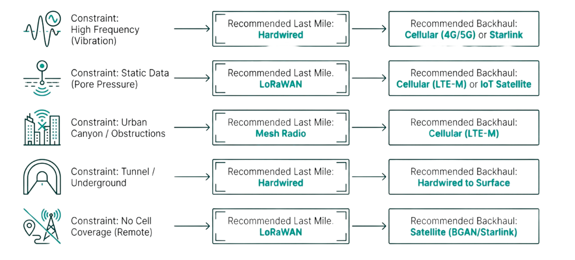
To use this matrix, first identify your project's primary constraint from the left-hand column (e.g., "Urban Canyon / Obstructions"). Then, follow the row across to find the recommended "Last Mile" and "Backhaul" technologies that are best suited to solve that specific challenge.
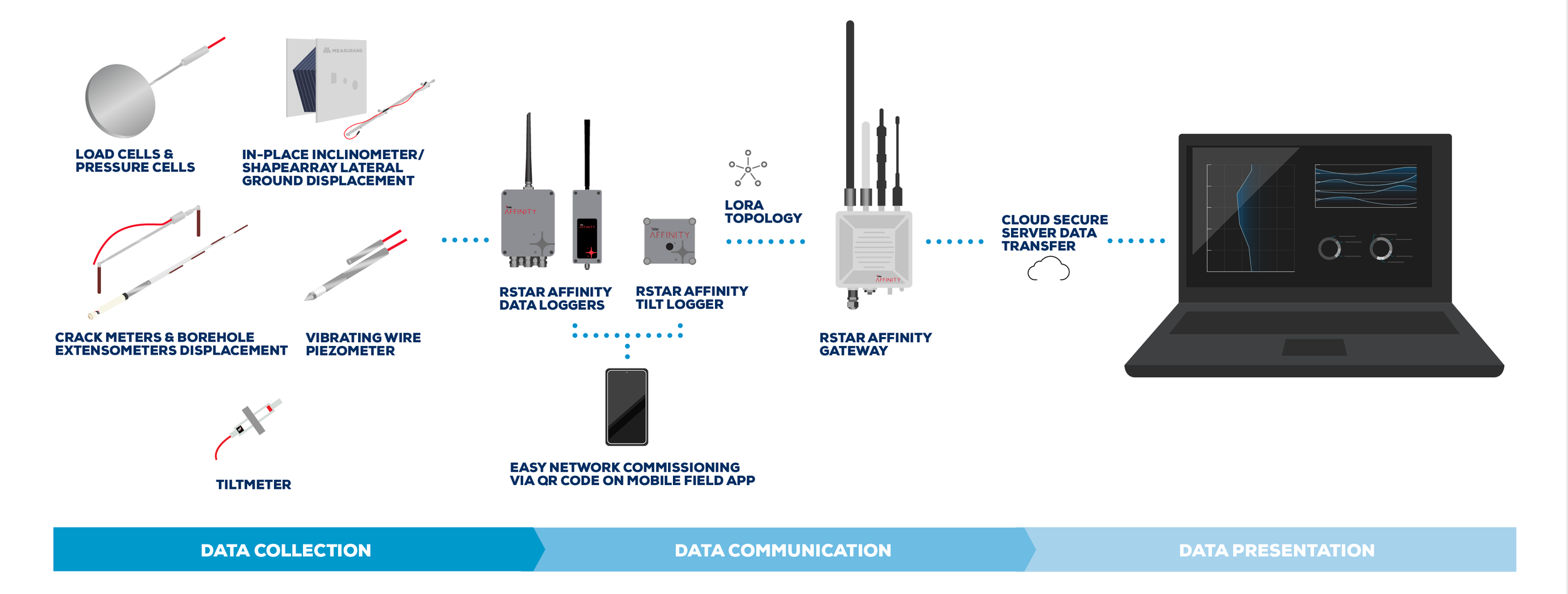
There is a number of manufacturers specializing in geotechnical monitoring and who can provide data acquisition systems that meet the “Last Mile” and “Backhaul” features described in the previous sections.
The figure below, courtesy of Orica Digital Solutions-RST Instruments, illustrates one such architecture with lithium battery powered node loggers for the “Last Mile”, communicating using LoRa radios with a line of sight range of up to 14 km to a central gateway with “Backhaul” cellular or satellite interface to a cloud server hosting a software for data management, visualization, alarming and reporting.
Guiding Principles and Conclusion
The most important principle in designing a geotechnical data acquisition system is that there is no "one size fits all" solution. Every project has a unique combination of physical, technical, and commercial constraints that must be carefully considered. A successful and robust monitoring plan is one that is tailored to the specific risks and realities of the site.
As you move forward in your designs, keep these key takeaways in mind:
Embrace Hybrid Solutions: A robust monitoring plan often combines multiple technologies. It is common and effective to use Hardwired systems for critical, high-speed zones, LoRaWAN for the perimeter background monitoring, and a Cellular Gateway with a Satellite backup for the most critical alarm pathways.
Focus on the Pipeline: The ultimate goal is not just the collection of sensor data. It is the design and construction of a resilient, end-to-end data pipeline that you can trust to deliver information reliably under all conditions.
The Purpose of Instrumentation: Never lose sight of the fundamental mission. The goal is to ensure that when the ground moves, the decision-maker knows about it instantly—regardless of where they are on the planet.